My GT2 belt arrived a few days ago, but I wanted to successfully upgrade my Extruder Head before moving on to something else. This time I am planning to install Proto-Plastik’s anti-sag truss.
Anti-Sag Truss parts
Over the past couple of weeks I have printed out the parts for the anti-sag truss. During that time I printed the parts with various levels of printer upgrades, and different colors of filament.
Part 1 – Left end
 There are three printed parts for the left end of the anti-sag truss. Construction is very straight-forward. Connect the left end of the anti-sag truss to the left end axle retainer with two M3-10mm screws, be careful not to over-tighten the screw.
 Next, put the idler pulley in the left end and fasten in place with an M8-30mm screw.
If you over-tighten this you will have to replace it with an M8-35mm screw and nut, so take care.
Step 2 – Right end
 There are also three parts in the assembly of the right end of the anti-sag truss. Connect the right end of the anti-sag truss to the axle retainer using two M3-10mm screws.
P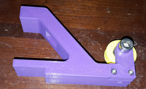 lace the idler pulley assembly into the right end and fasten in place with another M8-30mm screw.
Step 3 – Lower idler pulley
 The last part of the anti-sag truss is the lower idler pulley which connects to the z-index base part. The picture of the parts is missing the M8-20mm screw.
Assembly is extremely simple. Put the bottom shell of the lower idler pulley assembly down on the table, then place the idler pulley where it belongs.  Finally place the top half of the shell down on top of the assembly and fasten it down using four M3-8mm screws. Then thread the M8-20mm screw through the idler pulley to complete the part.
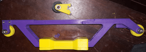
Step 4 – Assemble the handle
 Using the parts you already put together and the three parts for the handle, you now need to assemble the handle for the printer.
- Fasten the handle top and bottom parts using four M3-20mm screws
- Fasten the left end of the assembly into the handle from step #1 using two M4-20mm screws
- Fasten the right end of the assembly into the handle from step #1 using two M4-20mm screws
- Finally put the truss center piece into the assembly created in step #3. Make sure the holes line up between the assembly and the center piece, if not, flip it 180°. Fasten the truss center piece and assembly using four M3-8mm screws
 Step 5 – Install the anti-sag truss
At this point you should have both parts needed for your printer. You can remove the wooden handle from the printer and fasten down the handle using the same M4-8mm screws that previously held the original handle.
Connect the lower idler pulley to the z-index housing on the printer. This part must be installed straight out from the 8mm drilled linear shaft the goes through the z-index housing. I bought a package of 8×1/2 self tapping screws to fasten the lower idler pulley, I drilled a starter hole using a Dremel, then drove the screws int the rest of the way to complete the installaion.
Next I connected a length of GT2 timing belt in the retainer on the right end of X-Gantry with the treads facing out, so the smooth side would roll over the pulleys. I may need to experiment with this, but it seemed most logical. The belt was then passed up over the pulley in the right end of the anti-sag truss, then through the square holes in the handle from right to left, over the pulley in the left end and around the lower idler pulley. Finally, I lightly tightened the belt down using the retainer on the left end of the X-Gantry.
I then zeroed my digital caliper between the top of the X-Gantry left end and the Anti-Sag truss. Because I only lightly tightened down the left retainer, I was able to lift the X-Gantry on the right side, and then pull the belt tighter one tooth at a time. I continued doing this until I found the tooth on the belt where my measurement with the caliper went from positive to negative.
Time for bed, and some more calibration cubes tomorrow…
Leave a Reply